Efficient Budget & Time: Commissioning a Battery Research Pilot Line
This Insight offers guidance on defining your battery research requirements to make an effective and informed decision on the equipment and materials required to commission a Battery Research Pilot Line. With over 30 years of experience, we have partnered with MTI Corp as their UK and European distributor to deliver cutting-edge solutions to numerous research institutes. Over this time, we've witnessed the evolution of battery technologies, and we are committed to supporting your research journey.
Choosing a Battery Research Line can seem overwhelming. The vast array of options and varying specifications can be confusing, and it can be difficult to even establish a starting point.
PI-KEM can support you to navigate this process, using our extensive experience in developing diverse lines in various battery research areas:
- Small coin cell lines (glovebox)
- Small pouch cell lines
- Cylinder cell lines
- Larger pre-production lines
We also have expertise in various technologies and materials:
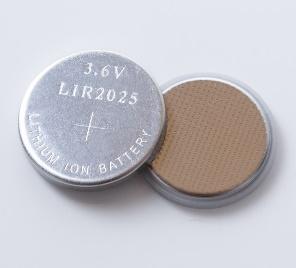
- Lithium-ion: The dominant technology in current research, powering devices from smartphones to EVs.
- Zinc Nickel: A mature technology with growing commercial viability.
- Sodium-ion: A promising alternative to lithium-ion, growing in popularity as a more sustainable and abundant resource. Our Sodium Chips streamline research by providing ready-made discs.

We've learned many valuable lessons, enabling us to identify equipment that maximises efficiency and minimises time and effort for your projects, ultimately providing the best possible battery line.
Stages of Battery Production
Any battery production line involves six core stages: Mixing, Coating, Calendaring, Slitting, Stacking, and Sealing. Here we outline the essential steps, and offer initial suggestions for equipment and materials, which can then be tailored for the type and scale of your manufacturing process.
Stage 1: Mixing
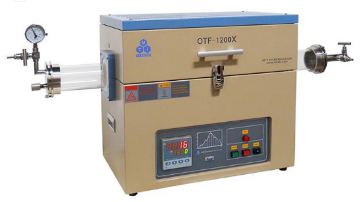
Mixing starts with material synthesis, often using a furnace to sinter the raw active materials for the cathode and anode. We offer a range of furnace options including:
- Tube furnaces (single zone or multi zone)
- Vacuum or high-pressure options
- Sliding, rotary and rocking tubes
- Ultrasonic spray pyrolysis for the synthesis of core shell nanoparticles
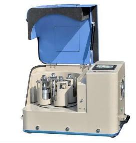
Following material synthesis, the active material is milled into smaller particles. Numerous options of mills are available, depending on particle size and whether the material is wet or dry. These include ball mills, vacuum mixers, and high shear mixers.
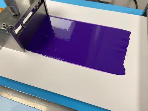
Stage 2: Coating
Coating is the process of applying a layer of active material to the foil. This can be done using a variety of methods, including:
- Doctor blade coating: The most basic method of film coating involves running a blade across the substrate to spread a solution evenly across the surface of the foil.
- Compact tape caster: This is a small-scale lab setup that uses a vacuum chuck to hold the foil in place and a variable speed film applicator to apply the active material. Also includes options for heating and UV light.
- Slot-die coating: The active solution flows through the ‘head’ of the coater as it moves across the foil surface, achieving uniform films on both rigid and flexible substrates.
- Roll-to-roll coaters: These are large-scale machines that can be used to coat large rolls of foil, using standard doctor blade, reverse comma blade, micro-gravure coating, slot die coating and some combinations of these.
The specific method used will depend on the type of battery being manufactured and the desired thickness of the active material layer.
Stage 3: Calendaring
- This is a critical part of producing electrodes, involving compressing the material through precise rollers to achieve a desired thickness and density.
- Important for electrode and cell uniformity, whilst also maximising energy density.
- The larger coating machines can also combine with either cold or hot calendaring, or film lamination.
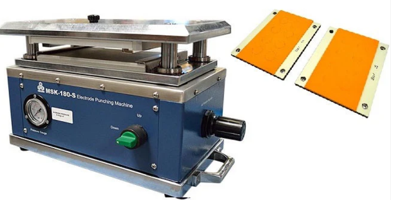
Stage 4: Slitting
Once the electrode materials have been made, the next important step is slitting, which is cutting the electrode materials into the correct shapes for different types of batteries.
- Coin cells are typically cut using disc cutters
- Handheld disc cutters are simple to use for small volumes to cell production, but they can be difficult to handle in a glove box for larger volumes
- For larger volumes, precision cutters or high-throughput pneumatic cutters can be used
- Most research applications use 20XX-sized coin cells as standard, but other size options are available
- Pouch cells can be cut using similar equipment to high throughput coin cells, but there are also options specifically for pouch cells.
- Standard sizes are 56 x 43mm and 58 x 45mm, but larger sizes up to 380 x 380mm are also available.
- Automatic roll-to-sheet cutting machines are available for high-volume production.
- Cylinder cells are made using either a semi-automatic slitting machine or a roll-to-roll slitter, depending on the size of the application. There are several options available for both machines to meet the specific requirements of the battery line.
- After the slitting stage, the cells may need to be dried in a vacuum oven - there are different sizes and multiple heating zones options available.
Stage 5: Stacking
- In this stage, the different components of the battery are assembled.
- For coin cells, stacking is a simple process involving assembling the pre-cut cathode, separator, anode, spacer and spring inside the coin cell case. The electrolyte can then be injected before the cell casing is closed.
- In pouch cells, the pre-cut anodes, separator film, and cathodes can be stacked together by hand. However, using a semi-automatic or fully-automatic stacking machine can improve precision and increase throughput.
- Cylindrical cells need the anode, separator and cathode to be wound together into a jelly roll before being inserted into the cylinder casing. This can be done with either a manual, semi-automatic or fully-automatic winding machine.
Once the electrodes are stacked, cylindrical and pouch cells need the current tabs to be welded on using an ultrasonic welder. This is a critical step, as it ensures that the cells can be connected to the external circuit.
Stage 6: Sealing
Sealing finalises the battery unit by securing components within the casing.
- Coin cells: After filling with electrolyte, sealing is performed using a hydraulic, pneumatic, or electric crimper, depending on the setup (e.g. pneumatic and electric are useful for preventing contamination of a glove box).
- Pouch Cells: Sealing is more complex and involves multiple stages:
- Initial sealing uses either standard pouch cases, or custom pouch cases formed with a pouch case machine and bespoke die.
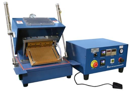
Options range from compact sealers and 3-in-1 sealers (pre-sealing, vacuum sealing, electrolyte diffusion/degassing) to 4-in-1 sealers with oxygen/moisture purging for improved SEI layer formation in solid state cells.
- Advanced automatic vacuum sealers can integrate electrolyte injection and diffusion, with various configurations for specific needs.s
- Cylinder Cells: Sealing involves grooving the case, deep welding the bottom electrode connection, electrolyte injection, and final sealing using crimpers (manual or automated for batch processing).
- For electrolyte injection, options include standard digital bottle dispensers or automated systems for pouch and cylinder cells, allowing vacuum injection with programmable settings.
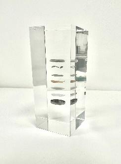
Once cell production is complete and the battery is fully functional, we provide support for testing processes. Our battery analysers, available in various configurations, automatically cycle cells and log data for analysis. For specialied research, tools like split test cells or Kapton window coin cells may also be valuable.
Project Planning with PI-KEM
At PI-KEM, we engage early in projects to fully understand both current and long-term plans, including any additional options under consideration. By recognising that plans can evolve, we aim to identify potential paths upfront, enabling us to collaborate effectively and explore balanced solutions. This ensures a tailored outcome that supports your research to its full potential.
Navigating Complexity
Time constraints often make equipment selection feel overwhelming, with numerous options leading to rushed decisions. Finding the best solution requires patience, perseverance, and openness to alternatives. Drawing on our experience across diverse projects—from small labs to high-end pilot line production —we can efficiently design bespoke, cost-effective solutions tailored to your unique needs.
A common mistake in equipment selection is over-specifying their requirements too early, often driven by focusing on high-end options without considering how they align with prior or subsequent processes.
- Over-Specifying: For pouch cell research, while a cutter supporting up to 380 x 380 mm might seem future proof, most facilities rarely need such large sizes. Upscaling all related equipment to match would significantly inflate costs, potentially diverting funds from more impactful investments.
- Under-Specifying: Alternatively, opting for cheaper equipment to maximize funding may lead to long-term issues. Limited functionality can render equipment obsolete during project scaling, necessitating costly replacements and hindering efficiency.
Comprehensive Support
Our role extends beyond equipment selection. We also supply:
- Lithium, sodium, and other chemicals
- Electrolytes
- Material sheets, foils, and foams
Consumables stocked in our warehouse:
- Safety testing equipment
- Wafers and substrates
- Other associated too
With our in-house expertise and strong supplier partnerships, we deliver optimised solutions to save you time, effort, and cost.